As stated above, Hall effect is observed even when there is steady state. Clearly it is a phenomenon different from induction which results from varying current or varying magnetic field.
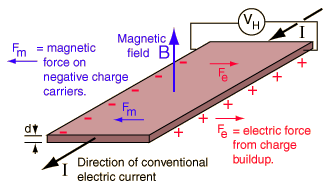
Lets understand the production of Hall Voltage in a flat conducting plate as shown in the picture below.

Let a current #I# flow through a conducting plate of thickness #d#. A perpendicular magnetic field #vecB# is applied as shown.
Electrons, which are the carriers here, experience a transverse force #vecF_m# due to the magnetic field and are pushed to one edge of the plate. This leaves the other edge deficient in electrons or positively charged and an electrical field #vecF_e# is created in the plate as shown. Thus potential difference #V_H#, called Hall Voltage is created between the two edges. Which can be measured with the help of a sensitive voltmeter.
Direction of magnetic force #vecF_M# can be ascertained with the help of right hand rule. One needs to remember that electrons are negatively charged and therefore, their velocity is in a direction opposite to that of the conventional current #I#. This also fixes the direction of electric field #vecF_H# produced due to Hall effect.
Hall effect is noticed in semiconductors as well. For #n# type semi conductors carriers being negatively charged electrons treatment is similar. In #p# type semi conductors carriers are considered holes which carry positive charge and are dealt with appropriately.
Calculations of Hall voltage:
Let #W# is the width of the conducting plate, current #I# be along #x# axis, #vec F_e# along #y# axis and #vecB# along #z# axis of a coordinate system. using Lorentz force equation for a charge #q#
#mathbf{F} = mathbf{F_E}+mathbf{F_M}#
#=qcdot[\mathbf{E} + (\mathbf{v} \times \mathbf{B})]#
Under steady state conditions no charges are moving in the #y#-axis direction. As the magnetic force on each electron in the #y#-axis direction is cancelled by an #y#-axis electrical force. The expression reduces to
#0 = E_y - v_x B_z# , ......(1)
where #-v_x# is the drift velocity of electrons constituting current #I#. Also noting that for a contant electric field #E=V/d#, we obtain
#E_y=-V_H/W#.....(2)
From (1) and (2) we obtain #V_H=v_xB_zW#.......(3)
Recalling that current is given as #I_x=ndW(-v_x)(-e)#
where #n# is charge carrier density, #d xx W# is area of cross-section for the current flow, and #-e# is the charge of each electron. Substituting value of #v_x# in (3) we obtain
#V_H=I_x/(ndWe)B_z W=(I_xB_z)/(nde)#

