Can someone pls show me the VR (Voltage-Resistance) Graphs for an NTC thermistor, filament lamp and conductors?

How do these components' resistances vary with voltage?

1 Answer
Apr 28, 2018

Please see below.

Explanation:

.

Let's take a look at an NTC thermistor circuit:
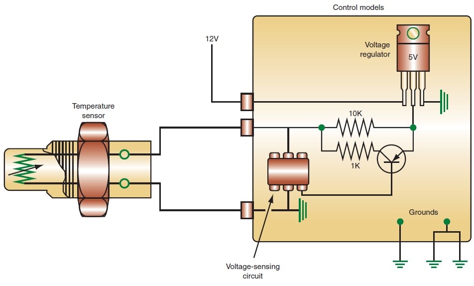
enter image source here

The input of #12# volts goes through a voltage regulator that regulates and supplies #V_s=5# volts as supply voltage to the circuit. The temperature sensor measures the change in the output voltage as a result of the change in the resistance of the element in the sensor and converts it into the desired unit .

We know that the circuit has a fixed resistor #(R)# of #10kOmega# and the resistor in the thermistor element #(R_t)# also has a value of #10kOmega# at the nominal ambient temperature of #21^@ C#.which varies with temperature.

The output voltage #V_o# varies as #R_t# varies. The relationship between them is:

#R_t=R(V_s/V_o-1)#

It is difficult to find the Voltage-Resistance graph of an NTC thermistor in books but we can develop it here. We will designate the horizontal axis as the #V_o#-axis and the vertical one as the #R_t#-axis.

Furthermore, in order to obtain a reasonably clear scale, we will consider the two resistances in the equation in units of #10KOmega# instead of #Omega#. This is like dividing both sides of the equation by #10000#. As such, our equation becomes::

#R_t=R(5/V_o-1)# or

#R_t/R=5/V_o-1# which we will graph.

The graph will be:

enter image source here

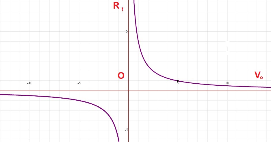
But since we are dealing with positive voltages only, we will concern ourselves with the right hand side of the graph where both #V_o# and #R_t# are positive. We will also limit the domain to #0 <= V_o <= 5#. Therefore, we will have:

enter image source here

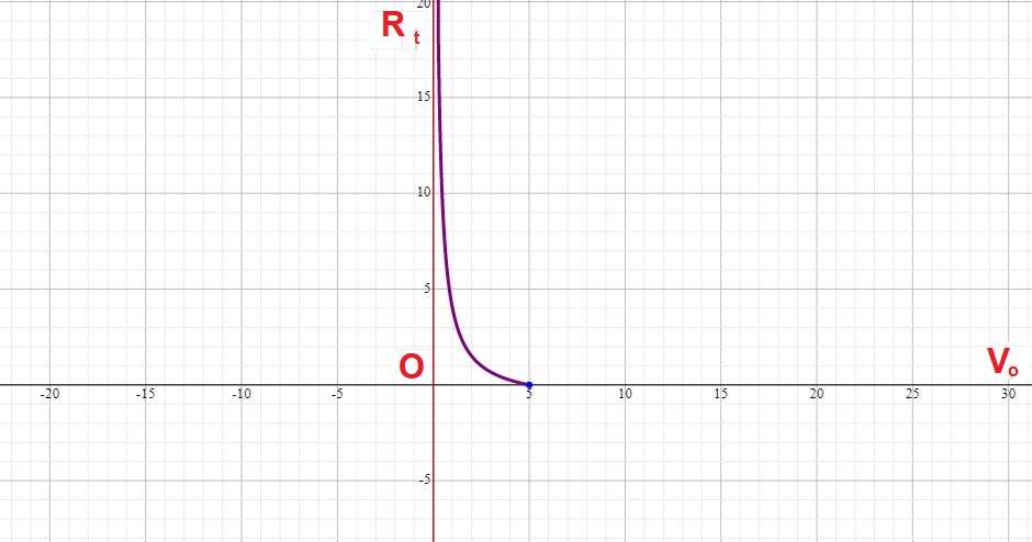
As the graph shows, when #V_o=0#, #R_t=oo# and when #V_o=5#, #R_t=0#. In between these values, the graph shows how the output voltage varies as the resistance of the thermistor element changes.

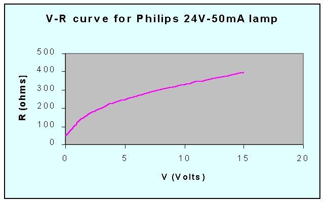
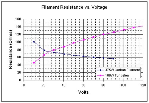
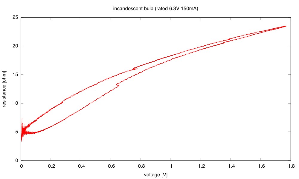
As far as filament lamps go, here are some graphs:

enter image source here

enter image source here

enter image source here

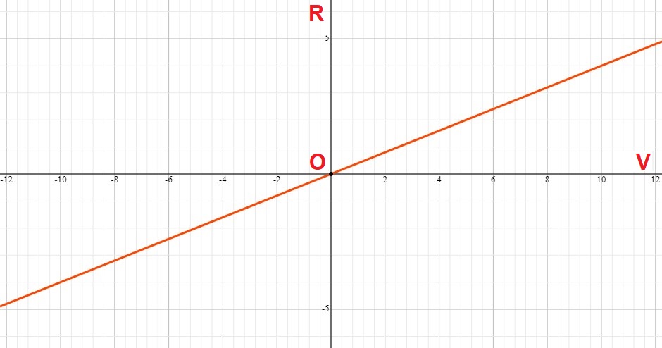
As far as metallic conductors go, their voltage-current, current-resistance and voltage-resistance relationships are linear and their graphs are straight lines that go through the origin. They are called Ohmic conductors:

enter image source here

Hope this helps.