How do I find the Voltage on these 2 diagrams?
1 Answer

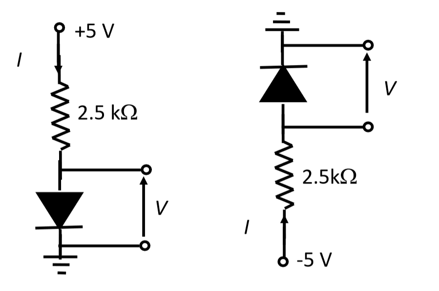
For the circuit on the left, the diode is forward biased, so we expect the voltage across the diode to be approximately
For the circuit on the right, the diode is reverse biased, so the voltage on the diode is
Explanation:
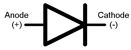
This question tests your knowledge of how diodes operate. A diode is a device that only allows current to flow in one direction, which is the direction of the "arrow", from the Anode to the Cathode
For an ideal diode in a circuit, if the voltage of the Anode is higher (more positive) than the voltage of the Cathode then the diode will allow current to flow and you can replace the diode with a short circuit (a wire). This is called "forward bias". If the voltage of the Anode is lower (more negative) than the Cathode, the diode stops current from flowing and you can replace it with an open circuit (i.e. set the current to zero). This is called "reverse bias".
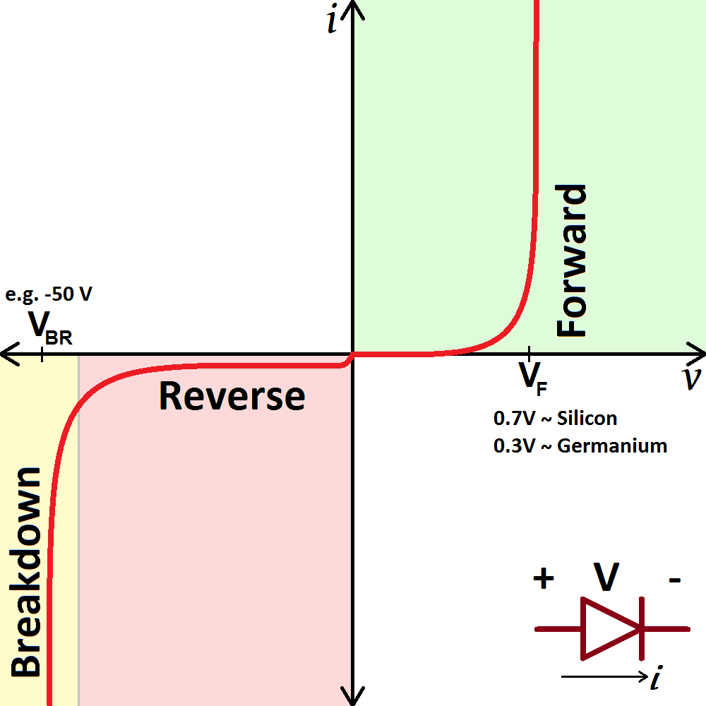
For a real diode the operation is close to the same, but when forward biased, the voltage across Anode to the Cathode must be higher than a material dependent "threshold voltage" or "forward voltage" for current to flow. In the case of a real diode in forward bias we replace it with a voltage source equal to the forward voltage
For a real diode in reverse bias, there is also a leakage current, which is normally so small that we ignore it. Also, there is usually a limit to how much reverse bias we are allowed to apply called "breakdown" which is usually very high so we can also ignore it for this question.
For the circuit on the left, we see that the diode is in forward bias, since the voltage on the anode is more positive (5V minus the voltage drop across the resistor) than the cathode (ground). The voltage is higher than the expected threshold voltage, so the current should flow, and we expect the voltage across the diode to be approximately
For the circuit on the right, the voltage on the cathode is more positive than the anode, so the diode is reverse biased. We can set the current to zero which means there is no voltage drop across the resistor which means the voltage on the anode is
