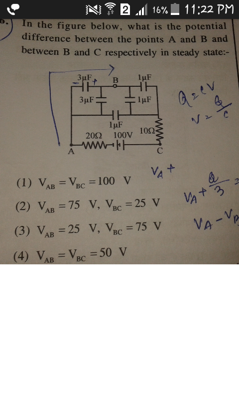
In the steady state, all currents will have stopped, therefore we can ignore the resistors.
Note that both of the 3 mufarad capacitors have a terminal that is common with the negative side of the battery (ignoring the 20 Omega resistor). And the other terminal of those capacitors are both directly connected to point B. Therefore they are in parallel with each other yielding a capacitance of 6 mufarad.
Note that both of the 1 mufarad capacitors have a terminal that is common with the positive side of the battery (ignoring the 10 Omega resistor). And the other terminal of those capacitors are both directly connected to point B. Therefore they are in parallel with each other yielding a capacitance of 2 mufarad.
The charges are distributed so that the charges on the plates of the 2 pairs of capacitors directly connected to B are -q, +q, B, -q, +q left to right. The formula relating capacitance, charge, and voltage is
V= q/C.
The sum of the voltages V_"AB" and V_"BC" must be 100 V because the resistors have no current in them. The 2 equivalent capacitances are 6 mufarad and 2 mufarad (left to right on the circuit diagram). The formula is V= q/C. Therefore the voltage V_"BC" must be the greater voltage by the ratio that 6 is greater than 2.
Therefore the answer is (3) V_"AB" = 25 V and V_"BC" = 75 V.
I hope this helps,
Steve


