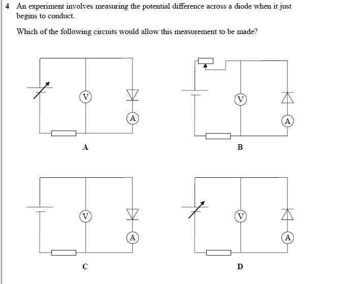
How does this allow us to measure the potential difference across a diode?
Why is the answer D pls?

Why is the answer D pls?

1 Answer
I do not agree that the correct answer is D. Circuit A will allow you measure the forward biased potential difference across a diode. Circuit D will allow you to measure the reverse breakdown voltage.
Explanation:
The meaning of schematic symbols is not entirely standard; this is most especially true for the symbol for a variable voltage source. I assume that the upper terminal of the variable source in diagrams A and D is the positive terminal. For a diode to be forward biased, the positive terminal of the voltage source must be connected to the anode of the diode. The anode of the diode is the side shaped like the head of an arrow; this is why I disagree that the correct answer is D.
Using diagram A:
- Set the voltage source to 0
- Slowly increase the voltage, until the ammeter shows measures a small current.
- Observe the voltage displayed on the voltmeter (the expected value is
#~0.6" v"# ).
If you connect the diode as in the circuit D, the diode will be reverse biased and will not conduct until the potential difference is a much larger number. One should not allow this condition to exist for more than a few seconds because the destruction of the diode can occur.
