Question #13465
1 Answer
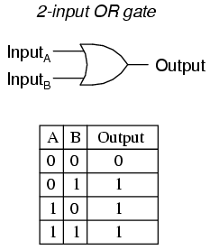
Truth table of a Two input OR Gate
Explanation:
Whenever a positive voltage is applied at the input of any of the diodes, it is forward biased and conducts electricity in the direction of the junction shown. This flow of current produces voltage across the resistance R which is detected at point C.
Assuming that the presence of voltage represents digit 1, and its absence represents digit 0.
-
No positive voltage at the input of either A or B. None of the diodes is forward biased. No current flows through resistance R. No voltage detected at C
A = 0, B = 0, C = 0
Gives us the first line of the truth table. -
No positive voltage at the input of A. Positive voltage at the input of B. Only diode B is forward biased. Current flows through resistance R. Positive voltage detected at C
A = 0, B = 1, C = 1
Gives us the second line of the truth table. -
Positive voltage at the input of A. No voltage at the input of B. Only diode A is forward biased. Current flows in resistance R. Positive voltage detected at C
A = 1, B = 0, C = 1
Gives us the third line of the truth table. -
Positive voltage at the input of A. Positive voltage at the input of B. Both diodes A and B are forward biased. Combined current flows in resistance R. Positive voltage detected at C
A = 1, B = 1, C = 1
Gives us the fourth line of the truth table.
Truth table is verified for a OR gate.
