Question #38f0d
1 Answer
Capacitor (originally known as condenser), is a passive device to store charge temporarily as in an static electric field.
Explanation:
A capacitor consist of one or more pairs of conductors separated by a dielectric, which could be vacuum, air, insulator, glass, paper or ceramic, etc.
In its simplest form it comprises two parallel conducting plates separated by non-conducting region that is called dielectric. The capacitance
Capacitance that is proportional to the area
A capacitor is assumed to be self-contained and isolated, with no net electric charge and no influence from any external electric field. The conductors thus hold equal and opposite charges on their facing surfaces, and the dielectric develops an electric field. In SI units, a capacitance of one Farad means that charge of one Coulomb on each conductor causes a voltage of one volt across the device. Common values of capacitors are micro-farads, pico-farads and nano-farads.
Capacitance
General uses of Capacitors are
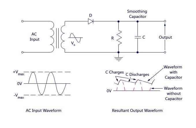
- As smoothing capacitor, in power supply applications which convert signal from AC to DC.
- For storing Energy.
- As a coupling capacitor as it blocks DC current and allows AC to pass in circuits.
- In tuning circuits, as in radio systems by connecting them to LC oscillator and tuning to the desired frequency.
- As timing capacitors due to the fixed charging and discharging time of capacitors.
- For power factor correction in electrical applications.
.-.-.-.-.-.-.-.-.-.-.-.-.-.-.-.-.-.--.-.-.-.-.-.-.--.
Example of Use # 1.
Notice the change in the shape of output waveform when a capacitor is added in the circuit of a half wave rectifier, figure above.
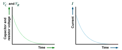
When only resistance is present in a circuit, the current waveform will be a starlight line as calculated from the Ohm's law. Notice the current versus time plotted when a capacitor is added (RC) in the figure below.

In the figure below, the shape of current when resistance and inductance are connected in series in a circuit (RL).

Compare with the current waveform when a capacitor is added in series (RLC).
.
